Problem statement: why most commercial LED installs fail the structural test
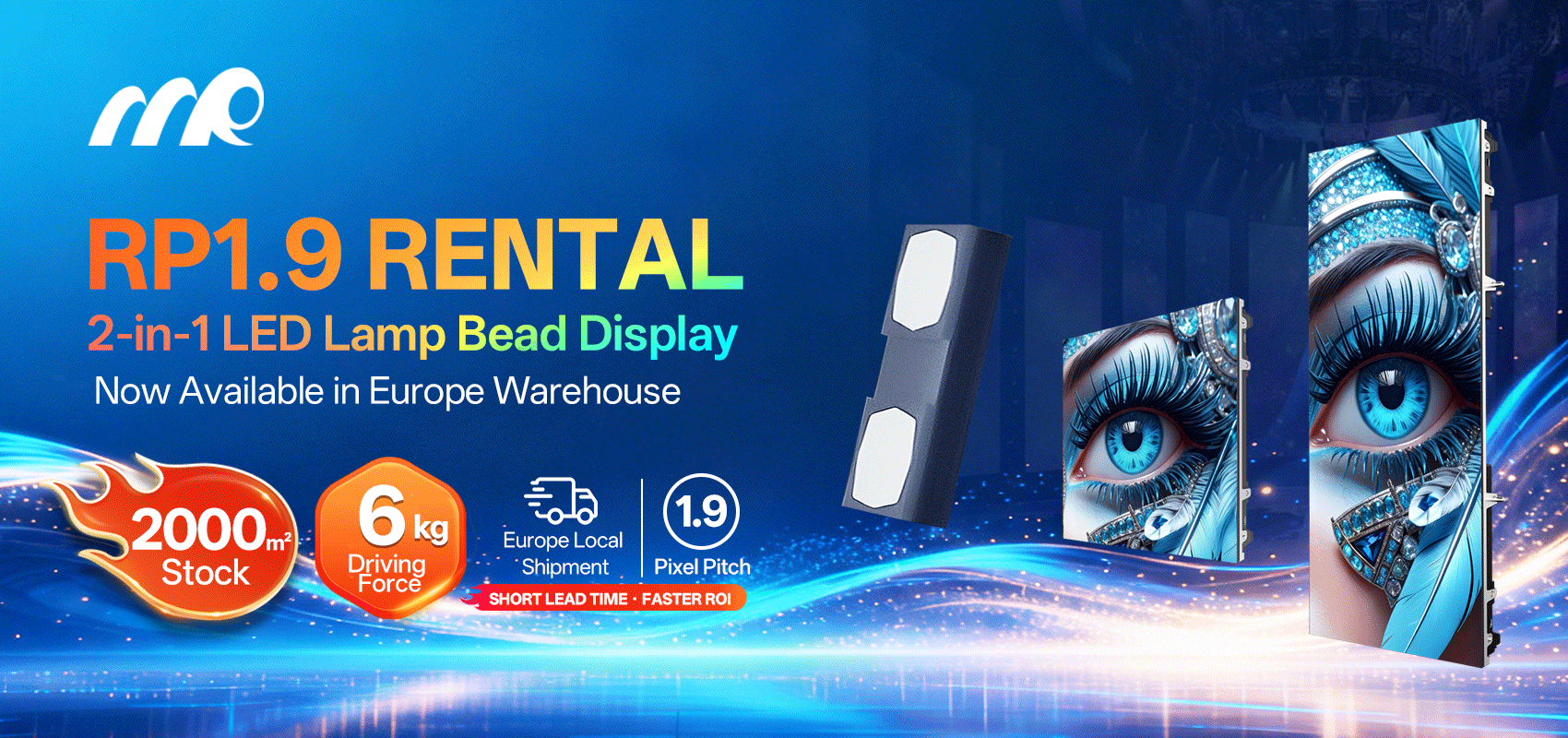
Large-format panels mounted with fast-lock frames often transfer unexpected lateral and uplift forces to their suspension system. When designers assume uniform loads instead of accounting for gusts, dynamic amplification, and asymmetric payloads, the outcome is bent brackets, compromised suspension points, or full panel collapse. Early-stage specification should reference the specific product—start with the unit geometry and mass of a small led screen—and calibrate the structural model for ensemble behavior. For direct view LED displays, aerodynamic drag coefficients and panel spacing matter as much as bracket strength.
Diagnosing the structural risk
Assessments must be data-driven and reproducible. Use wind-load maps from ASCE 7-16 and local code (or Eurocode EN 1991-1-4 where applicable) to define basic wind speed, then apply site factors for exposure and topography. Extract these parameters: basic wind speed, exposure category, gust factor, and tributary area per panel. Industry terms here include wind load, gust factor, and tributary area—all central to an analyzable load case. Document mounting details: number and spacing of suspension points, fast-lock connector engagement depth, and the mass per cabinet (payload). These inputs make the difference between conservative design and reckless assumption.
Quantifying wind loads and safety factors
Compute design pressures using code formulas, then superimpose dynamic effects: a 30–50% increase often suffices for unshielded façades or roof-edge installations. Apply a rigging safety factor (minimum recommended 5:1 for temporary overhead work, 3:1 for permanent engineered mounts where code allows) to every primary structural element: suspension hardware, bolts, and load-bearing frames. Include terms such as rigging safety factor, suspension points, and payload capacity. Account for eccentric loading when panels are not flush—torsion on brackets can dominate shear in the fast-lock interface.
Rigging practice and layout best practices
Designers should clamp to primary structure, not to secondary facades. Specify load-rated hardware (WLL and MBS clearly marked), position redundant suspension points, and route supplementary guy lines where possible. Use spreader bars to reduce point loads and stiffen the array; aim for uniform load distribution across fast-lock connections. Inspect torque values and locking mechanisms on-site—fast-lock connectors offer speed but can mask insufficient engagement length and worn teeth.
Common mistakes and believable alternatives
Typical errors include: underestimating gusts, ignoring temporary live loads (maintenance crews), and relying on untested onsite welds. Another frequent misstep is copying indoor rigging details for outdoor installations—materials corrode and stiffness changes. Alternatives: switch to modular frames with certified load paths, or adopt hybrid suspension with both rigid hangers and tensioned guy wires. —A redundant tie-off can mean the difference between repairable damage and a safety incident.
Inspection, testing, and project anchoring
Implement a staged verification plan: shop-check the fast-lock engagement and test a representative assembly with an instrumented pull test at 150% of design load. Perform a post-install wind-read verification if possible; recorded gusts that exceed code assumptions should trigger an immediate engineering review. Real-world anchor: damage reports after Hurricane Sandy (2012) highlighted that many outdoor screen failures were due to underestimated wind pressures and absent redundancy—those case studies drove changes in inspection protocols across stadium and urban deployments.
Closing advisory: three golden rules for mechanical rigidity and rigging
1) Always model dynamic wind effects and apply conservative gust amplification before choosing hardware. Measureables: design pressure and expected gust speed. 2) Use minimum safety factors appropriate to the application—5:1 for temporary overhead, ≥3:1 for permanent engineered systems—and verify with pull tests. Record Working Load Limit (WLL) and Minimum Breaking Strength (MBS). 3) Design for redundancy: redundant suspension points, corrosion-resistant hardware, and a documented inspection schedule that includes fast-lock engagement and torque records.
These rules reduce field surprises and improve uptime for complex direct view LED displays; practical engineering prevents most failures. MR LED. —solid practice, less risk.