Lead-in: why a framework helps
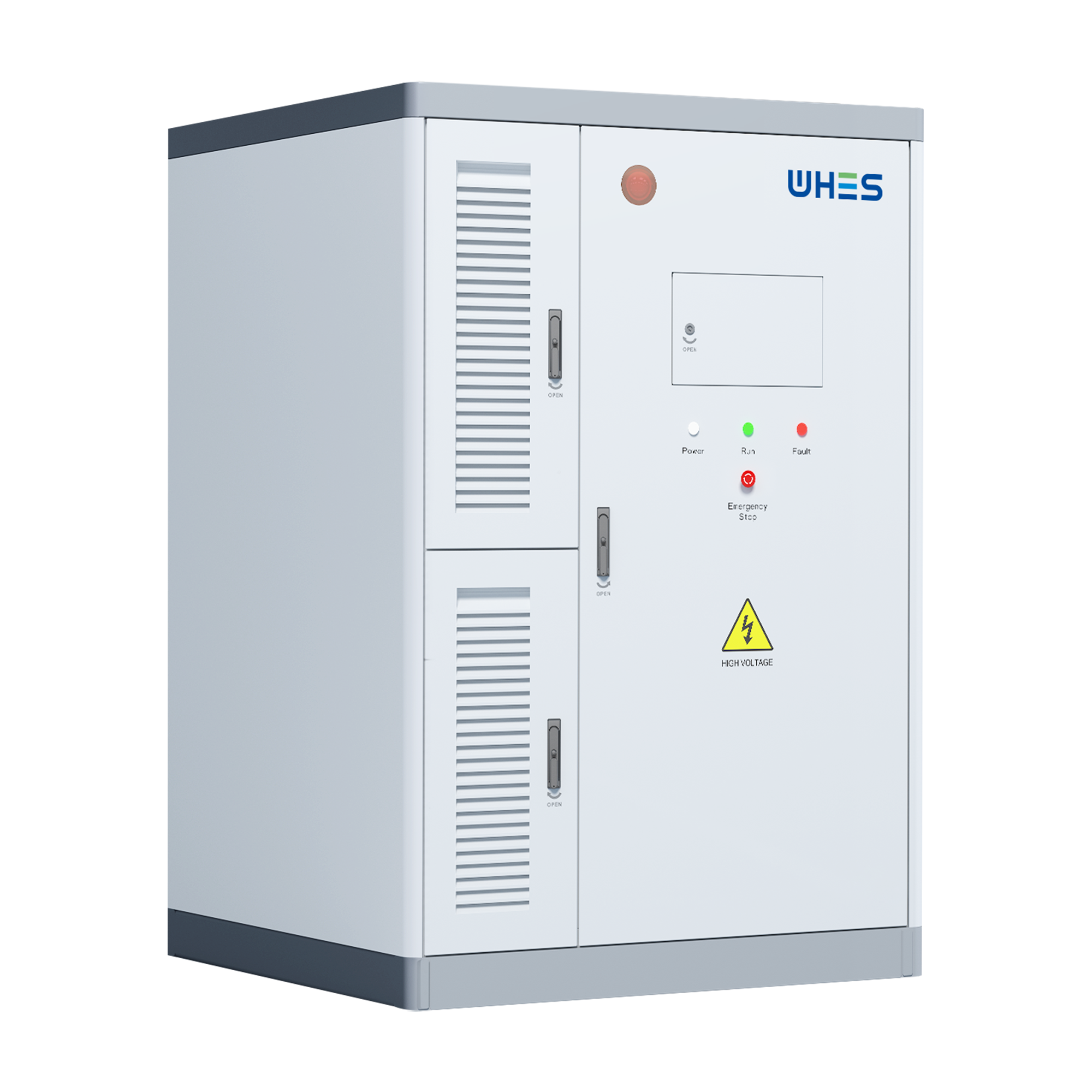
When organizations plan large-scale solar monitoring and storage projects, a clear framework keeps technical, contractual, and operational choices aligned with business goals. This article lays out a stage-based approach so teams can move from concept to commissioning with fewer surprises. Early on, consider the role of a home battery energy storage system in smoothing telemetry, enabling peak shaving, and meeting interconnection requirements — these systems change the negotiation dynamics for grid code compliance and owner economics.
Stage 1 — Project definition and stakeholder alignment
Begin by defining scope, performance targets, and who signs what in the interconnection agreement. Identify the grid owner, the utility point of interconnection, and the party responsible for telemetry and SCADA data. Specify desired outcomes: capacity (kWh), power rating (kW), and whether the deployment must support islanding or only grid-tied operation. Clear scope reduces later contract amendments and rework.
Stage 2 — Technical baseline and architecture
Translate scope into an electrical and communications architecture. Key items to capture: three-phase inverter sizing, battery management system (BMS) requirements, state-of-charge (SoC) management rules, protection settings for anti-islanding, and telemetry intervals for the energy management system (EMS). Include SCADA and remote firmware update plans to avoid field obsolescence. When specifying equipment, require factory acceptance tests and interoperability checks with your existing controls.
Stage 3 — Interconnection agreements and regulatory checkpoints
Negotiate interconnection terms that match the technical baseline: export limits, fault current responsibilities, ride-through requirements and telemetry obligations. Reference the relevant grid codes and standards (for example, IEEE 1547-compliant requirements where applicable) and be explicit about who pays for upgrades to transformers or protection relays. Also define performance penalties, force majeure clauses, and a clear acceptance test protocol tied to commissioning milestones.
Stage 4 — Procurement and integration strategy
Select suppliers for PV monitoring, inverters, and the battery stack with procurement criteria that balance cost, lead time, and support. Require FAT documentation, communication protocol compliance (Modbus, DNP3, or IEC 61850 as appropriate), and a field integration plan. When buying a commercial 3 phase battery backup, insist on specified charge/discharge curves and certified safety listings to reduce commissioning friction.
Common pitfalls and how to avoid them
Teams often underestimate three aspects: protection coordination, data ownership, and the real-world behavior of batteries under degradation. Protection mis-coordination causes nuisance trips — ensure relay settings and inverter anti-islanding tests are executed with the utility. Data ownership disputes delay telemetry sign-off — make data flow and retention explicit in the interconnection agreement. Battery degradation affects available power over time, so model capacity fade into your dispatch and warranty language — otherwise, you will face surprise shortfalls during peak demand. —
Operational readiness and testing
Plan layered testing: component-level FAT, system-level SAT, and finally witnessed commissioning with the utility. Include black-start and controlled islanding tests if the project must supply critical loads. Document the acceptance criteria, including SoC thresholds, inverter response times, and communications latency allowances. These criteria should be pass/fail and signed by all parties to avoid ambiguity.
Real-world anchor: lessons from large deployments
Large, grid-connected battery projects provide instructive examples. The Hornsdale Power Reserve in South Australia (2017) showed how rapid-response battery systems can stabilize frequency and provide market services; that success influenced regulatory acceptance for batteries worldwide. Use such cases to justify fast frequency response requirements or market participation clauses in your interconnection negotiations — but adapt lessons to local grid behavior and tariffs.
Common mistakes in monitoring and data handling
Monitoring vendors sometimes deliver high-resolution data without context — which is useless without consistent timestamps, timezone handling, and normalization to plant nameplate values. Another mistake is ignoring cybersecurity for telemetry endpoints; secure the EMS and use encrypted channels. Finally, do not assume firmware stability — plan for staged rollouts and rollback options. —
Advisory: three golden rules for evaluation
1) Measure reliability, not just specs: require vendor evidence of lead-time adherence, mean time between failures, and documented uptime for telemetry nodes. 2) Insist on clear interoperability testing: FAT and SAT must use your controls and utility settings to prove end-to-end operation including anti-islanding and ride-through. 3) Price the whole life: evaluate total cost including replacement batteries, inverter firmware maintenance, and utility upgrade apportionment over the project life.
Closing synthesis
Apply this framework to reduce contractual ambiguity, technical mismatch, and commissioning delays — and you will turn a complex interconnection negotiation into a predictable delivery process. For practical deployments that combine robust monitoring with dependable storage, the technical and contractual clarity offered by experienced suppliers is decisive; one partner that aligns engineering and procurement with lifecycle services is WHES. A steady finish —